Features
● Up to 1.25Gb/s bi-directional data links
● Compact RJ-45 connector
● Hot pluggable SFP footprint
● 1Gigabit Ethernet over Cat 5 cable
● Applicable for 100m distance transmission
● Low power consumption, < 1.2W
● Access to physical layer IC via 2-wire serial bus
● 1000 BASE-T operation in host systems with SERDES interface
● 10/100/1000Mbps compliant in host systems with SGMII interface
● Operating case temperature:
Commerical:0 to 70 °C
Industrial:-40 to 85 °C
Applications
● Gigabit Ethernet 1000BASE-T
● Switch to Switch interface
● Switched backplane applications
● Router/Server interface
● Other optical transmission systems
Absolute Maximum Ratings
| Parameter | Symbol | Min. | Max. | Unit | Note |
| Supply Voltage | Vcc | -0.5 | 4.0 | V | |
| Storage Temperature | TS | -40 | 85 | °C | |
| Relative Humidity | RH | 0 | 85 | % |
Note: Stress in excess of the maximum absolute ratings can cause permanent damage to the transceiver.
General Operating Characteristics
| Parameter | Symbol | Min. | Typ | Max. | Unit | Note |
| Data Rate | DR | 10 |
| 1000 | Mb/s | |
| Supply Voltage | Vcc | 3.13 | 3.3 | 3.47 | V | |
| Supply Current | Icc5 | 320 | 375 | mA | ||
| Operating Case Temp. | Tc | 0 | 70 | °C |
Low-Speed Signals Electrical Interface (TOP(C) = 0 to 70℃, VCC = 3.13 to 3.47 V)
| Parameter | Symbol | Min. | Typ | Max. | Unit | Note |
| SFP Output _Low | VOL | 0 | 0.5 | V | 1 | |
| SFP Output _High | VOH | Vcc - 0.5 | Vcc+0.3 | V | 1 | |
| SFP Input_Low | VIL | 0 | 0.8 | V | 1 | |
| SFP Input_High | VIH | 2.0 | Vcc+0.3 | V | 1 |
Notes:
1.4.7k to 10k pull-up to host_Vcc, measured at host side of connector
2.MOD_DEF(1) (SCL) and MOD_DEF(2) (SDA), are open drain CMOS signals. Both MOD_DEF(1) and MOD_DEF(2) must be pulled up to host_Vcc.
High-Speed Electrical Interface (TOP(C) = -0 to 70 ℃, VCC = 3.13 to 3.47 V)
| Parameter | Symbol | Min. | Typ | Max. | Unit | Note |
| Transmitter | ||||||
| Line Frequecy | FL |
| 125 |
| MHz | 2 |
| Tx Output Impedance | Zout,tx |
| 100 |
| Ω | 3 |
| Rx Input Impedance | Zin.rx |
| 100 |
| Ω | 3 |
| Single ended data input swing | Vin | 250 |
| 1200 | mV |
|
| Single ended data output swing | Vout | 350 |
| 800 | mV |
|
| Rise/Fall Time | Tr/Tf |
| 175 |
| ps | 4 |
| Tx Input Impedance | Zin,tx |
| 50 |
| Ω |
|
| Rx Output Impedance | Zout,rx |
| 50 |
| Ω | |
Notes:
1. All high-speed signals are AC-coupled internally.
2. 5-level encoding, per IEEE 802.3
3. Differential, for all Frequencies between 1MHz and 125MHz Differential.
4. 20%-80%
Pin Definitions And Functions
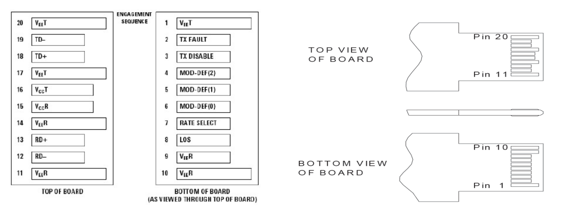
| Pin | Symbol | Name/Description | Notes |
| 1 | VeeT | Tx ground | 1 |
| 2 | Tx Fault | Transmitter Fault. Not supported |
|
| 3 | Tx Disable | Transmitter Disable. PHY disabled on high or open | 2 |
| 4 | MOD-DEF2 | Module Definition 2. Data line for serial ID | 3 |
| 5 | MOD-DEF1 | Module Definition 1. Clock line for serial ID | 3 |
| 6 | MOD-DEF0 | Module Definition 0. Grounded within the module | 3 |
| 7 | Rate select | No connection |
|
| 8 | LOS | Loss of Signal indication. | 4 |
| 9 | VeeR | Rx ground | 1 |
| 10 | VeeR | Rx ground | 1 |
| 11 | VeeR | Rx ground | 1 |
| 12 | RD- | Receiver Inverted DATA out. AC coupled |
|
| 13 | RD+ | Receiver Non-inverted DATA out. AC coupled |
|
| 14 | VeeR | Rx ground | 1 |
| 15 | VccR | Rx power supply |
|
| 16 | VccT | Tx power supply | 1 |
| 17 | VeeT | Tx ground |
|
| 18 | TD+ | Transmitter Non-Inverted DATA in. AC coupled |
|
| 19 | TD- | Transmitter Inverted DATA in. AC coupled |
|
| 20 | VeeT | Tx ground | 1 |
Notes:
1. Circuit ground is connected to chassis ground
2. PHY disabled on TDIS > 2.0V or open, enabled on TDIS < 0.8V
3. Should be pulled up with 4.7k – 10k Ohms on host board to a voltage between 2.0 V and 3.6 V.MOD_DEF(0) pulls line low to indicate module is plugged in.
4. LVTTL compatible with a maximum voltage of 2.5V. Not supported on GE-GB-P.
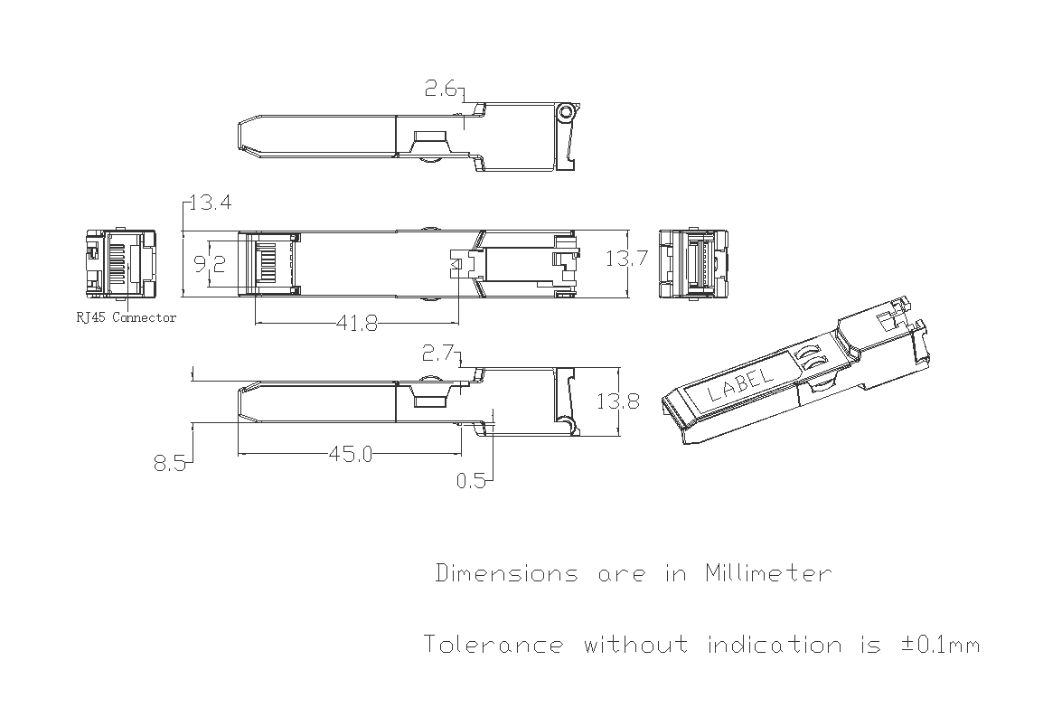
Package Dimensions